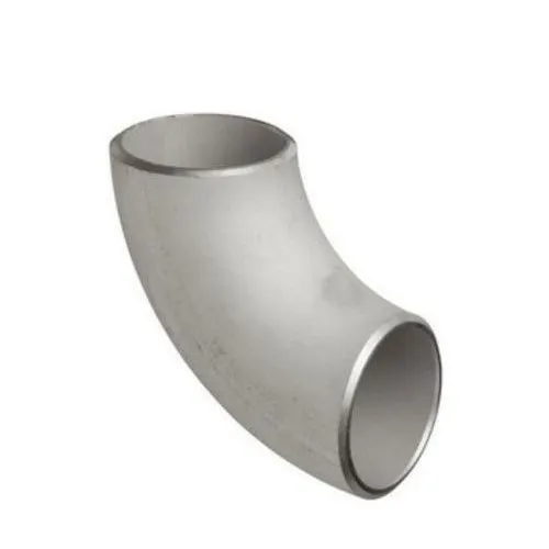
Butt Weld Elbow
Read More »
What is a butt weld elbow? A butt weld elbow is a type of pipe fitting used to change the

ASME B16.47 Class 400 Series B flanges are designed to operate in even higher-pressure environments compared to lower class flanges. Here is an overview of these flanges:
ASME B16.47 Class 400 Series B Flanges:
Commonly Used Materials:
– Carbon Steel (ASTM A105)
– Stainless Steel (ASTM A182)
– Alloy Steel (ASTM A182 F11, F22)
– Duplex Stainless Steel
– Nickel Alloys (Inconel, Monel, Hastelloy)
Common Dimensions and Specifications:
– Nominal Pipe Size (NPS) typically ranges from 26 to 60.
– Pressure rating is designated as Class 400.
Production Processes:
– Manufactured using precision machining, forging, or casting methods.
– Heat treatment processes are employed to enhance material properties for increased strength and durability.
Applications:
– Utilized in industries such as oil and gas, petrochemicals, chemical processing, and power generation.
– Specifically engineered for extremely high-pressure and moderate-temperature environments.
Frequently Asked Questions (FAQs):
1. What are the pressure-temperature ratings for different materials in Class 400 flanges?
– Pressure-temperature ratings vary among materials. For instance, carbon steel (ASTM A105) Class 400 flanges typically have pressure-temperature ratings up to 470°C (875°F). Stainless steel, alloy steel, and other materials have specific pressure-temperature ratings according to ASME standards.
2. Is interchangeability possible with other standard flanges?
– Generally, Class 400 Series B flanges can be interchanged with flanges of the same pressure class and compatible dimensions, but compatibility should be confirmed based on specific requirements.
3. What quality control measures are employed during manufacturing?
– Stringent quality checks encompass material traceability, dimensional inspections, and non-destructive testing (NDT) methods like ultrasonic and radiographic testing to ensure compliance with ASME standards.
4. Are there specific installation guidelines for these flanges?
– Yes, installation guidelines align with ASME standards and include bolt tightening sequences, gasket selection, and alignment procedures for secure and leak-free connections.
5. How do Class 400 Series B flanges perform in severe conditions compared to lower class flanges?
– Class 400 Series B flanges are designed to handle even higher pressures than lower class flanges. Their materials and properties ensure superior performance and durability in extremely high-pressure industrial environments.
ASME B16.47 Class 400 Series B flanges are specifically engineered to withstand exceptionally high pressures, making them suitable for critical applications where extremely high-pressure capabilities are necessary for secure and reliable connections within piping systems.
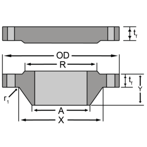
| Nominal Size | Outside Diameter | Min. Thickness [Note1] – WNF | Min. Thickness [Note1] – Blind | Length Through Hub | Hub Dia. Base [Note2] | Hub Dia. Top | Raised Face Dia. | Drilling – Bolt Circle Dia. | Drilling – No. of Bolt Holes | Drilling – Dia. of Bolt Hole | Dia. of Bolt | Min. Fillet Radius |
| (OD) | (tf) | (tf) | (Y) | (X) | (A) | (R) | (r1) | |||||
| 26 | 33.5 | 3.5 | 3.5 | 5.88 | 27.12 | 26 | 28 | 30.75 | 28 | 11⁄2 | 13⁄8 | 0.44 |
| 28 | 36 | 3.75 | 3.75 | 6.25 | 29.12 | 28 | 30 | 33 | 24 | 15⁄8 | 11⁄2 | 0.5 |
| 30 | 38.25 | 4 | 4 | 6.69 | 31.25 | 30 | 32.25 | 35.25 | 28 | 15⁄8 | 11⁄2 | 0.5 |
| 32 | 40.75 | 4.25 | 4.25 | 7.06 | 33.25 | 32 | 34.38 | 37.5 | 28 | 13⁄4 | 15⁄8 | 0.5 |
| 34 | 42.75 | 4.38 | 4.38 | 7.38 | 35.38 | 34 | 36.5 | 39.5 | 32 | 13⁄4 | 15⁄8 | 0.56 |
| 36 | 45.5 | 4.69 | 4.69 | 7.88 | 37.5 | 36 | 38.62 | 42 | 28 | 17⁄8 | 13⁄4 | 0.56 |
| 38 | 47.5 | 4.88 | 4.88 | 8.12 | 39.5 | 38 | 40.75 | 44 | 32 | 17⁄8 | 13⁄4 | 0.56 |
| 40 | 50 | 5.12 | 5.12 | 8.5 | 41.5 | 40 | 43 | 46.25 | 32 | 2 | 17⁄8 | 0.56 |
| 42 | 52 | 5.25 | 5.25 | 8.81 | 43.62 | 42 | 45 | 48.25 | 32 | 2 | 17⁄8 | 0.56 |
| 44 | 54.5 | 5.5 | 5.5 | 9.18 | 45.62 | 44 | 47.25 | 50.5 | 32 | 21⁄8 | 2 | 0.56 |
| 46 | 56.75 | 5.75 | 5.75 | 9.62 | 47.75 | 46 | 49.5 | 52.75 | 36 | 21⁄8 | 2 | 0.56 |
| 48 | 59.5 | 6 | 6 | 10.12 | 49.88 | 48 | 51.5 | 55.25 | 28 | 23⁄8 | 21⁄4 | 0.56 |
| 50 | 61.75 | 6.19 | 6.25 | 10.56 | 52 | 50 | 53.62 | 57.5 | 32 | 23⁄8 | 21⁄4 | 0.56 |
| 52 | 63.75 | 6.38 | 6.44 | 10.88 | 54 | 52 | 55.62 | 59.5 | 32 | 23⁄8 | 21⁄4 | 0.56 |
| 54 | 67 | 6.69 | 6.75 | 11.38 | 56.12 | 54 | 57.88 | 62.25 | 28 | 25⁄8 | 21⁄2 | 0.56 |
| 56 | 69 | 6.88 | 6.94 | 11.75 | 58.25 | 56 | 60.12 | 64.25 | 32 | 25⁄8 | 21⁄2 | 0.56 |
| 58 | 71 | 7 | 7.12 | 12.06 | 60.25 | 58 | 62.12 | 66.25 | 32 | 25⁄8 | 21⁄2 | 0.56 |
| 60 | 74.25 | 7.31 | 7.44 | 12.56 | 62.38 | 60 | 64.38 | 69 | 32 | 27⁄8 | 23⁄4 | 0.56 |
Notes
Dimensions are in inches.
1) The minimum flange thickness does not include the raised face thickness
2) This dimension is for the large end of hub, which may be straight or tapered.
3) WN ID/Bore is to be specified by purchaser.
4) For other details and tolerances see specification.
What is a butt weld elbow? A butt weld elbow is a type of pipe fitting used to change the
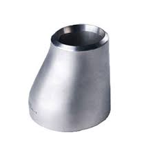
At SINO SPECIAL METAL, we provide high-quality butt weld eccentric reducers, essential fittings used in piping systems to seamlessly connect
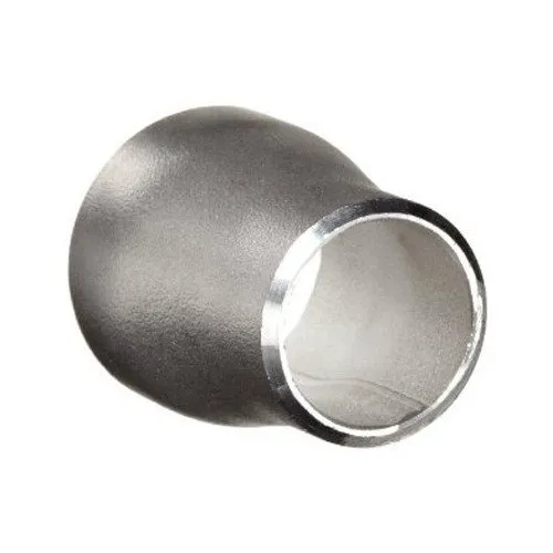
What is a Butt Weld Concentric Reducer At SINO SPECIAL METAL, we offer high-quality butt weld concentric reducers, pivotal components