Flanges, which are classified according to various country norms and connection types, are produced in different sizes according to the reasons for use.In this guide, I will explain everything you should know about Flanges.If you want to be an expert in metal flanges, read this guide to the end.
What is a Flange?
A flange is a projecting flat rim, collar, or rib on an object, serving for reinforcement or for attaching it to another object. In engineering and construction, flanges are often used to connect pipes, valves, pumps, and other equipment together. They provide a means for easy assembly and disassembly, as well as sealing to prevent leakage. Flanges come in various shapes and sizes, such as circular, square, or rectangular, depending on the application. They are typically bolted or welded onto the equipment they are connecting.
Characteristics of Flanges
Flanges have several characteristics that make them crucial components in various industries, particularly in piping systems. Some key characteristics include:
- Connection: Flanges provide a means of connecting pipes, valves, fittings, and other equipment in a piping system. They facilitate easy assembly and disassembly, allowing for maintenance, repair, and modification.
- Sealing: Flanges play a vital role in ensuring leak-proof connections between components. Gaskets or sealing rings are often placed between flange faces to create a tight seal, preventing fluid or gas leakage.
- Strength: Flanges are designed to withstand high pressure, temperature, and mechanical stress within a piping system. They are typically made from materials such as carbon steel, stainless steel, or alloy steel to provide strength and durability.
- Versatility: Flanges come in various sizes, shapes, and types to accommodate different piping requirements. They can be customized to fit specific applications and are available in standard dimensions according to industry standards (e.g., ASME, ANSI, DIN).
- Alignment: Flanges help align pipes and other components accurately during assembly, ensuring proper fit and function within the system. Alignment is crucial for maintaining structural integrity and preventing premature wear or damage.
- Accessibility: Flanges allow for easy access to components within a piping system for inspection, cleaning, and maintenance purposes. They can be quickly removed and reinstalled without extensive downtime.
- Corrosion Resistance: Flanges are often coated or made from corrosion-resistant materials to withstand the effects of harsh operating environments, chemicals, and corrosive fluids commonly found in industrial applications.
- Standardization: Flanges are manufactured according to industry standards and specifications to ensure compatibility and interchangeability between components from different manufacturers. Standardization facilitates seamless integration and reduces the risk of compatibility issues.
How Does Flange Connection Work?

Flange connections work by joining two components, typically pipes or valves, in a secure and leak-proof manner. Here’s how the process generally works:
Preparation: Before connecting the components, ensure that the flange faces are clean, smooth, and free from any debris, rust, or imperfections. This ensures a proper seal when the flanges are brought together.
Alignment: Position the two components (pipes, valves, etc.) that need to be joined so that their flange faces are aligned properly. Proper alignment is essential for creating a leak-free connection.
Insertion of Gasket: Place a gasket between the mating flange faces. The gasket is typically made of materials such as rubber, graphite, or PTFE (Teflon) and is selected based on the specific requirements of the application, including temperature, pressure, and fluid compatibility.
Bolting: Insert bolts through the holes in the flange faces and align them with the corresponding bolt holes on the opposite flange. The number and size of bolts used depend on the flange size and pressure rating.
Tightening: Gradually tighten the bolts in a crisscross pattern to apply even pressure across the flange faces. This helps ensure a uniform seal and prevents distortion of the flange or gasket. The tightening process is typically done in multiple stages, with the final torque applied according to manufacturer specifications or industry standards.
Verification: Once the bolts are tightened to the specified torque, visually inspect the connection to ensure that the flange faces are properly aligned and the gasket is seated correctly. Additionally, perform pressure testing, if required, to verify the integrity of the connection and confirm that there are no leaks.
Finalization: After verifying the connection, secure any additional components, such as nuts or washers, and apply any necessary coatings or sealants to further enhance the durability and performance of the connection.
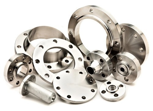
Common Types of Flanges and Their Uses
Flanges are integral components in piping systems, used to connect pipes, valves, pumps, and other equipment. They provide easy access for inspection, cleaning, and modifications. Here are some common types of flanges and their uses:
- Weld Neck Flanges: These flanges are designed with a long tapered hub that is welded to the pipe. They are used in high-pressure and high-temperature applications, providing excellent strength and stress distribution.
- Slip-On Flanges: Slip-on flanges have a bore slightly larger than the outside diameter of the pipe. They are slipped over the pipe and then welded on both sides to provide strength and prevent leakage. They are commonly used in low-pressure and low-temperature applications.
Socket Weld Flanges: These flanges have a recessed area (socket) that fits over the pipe. They are welded around the joint, providing good strength and flow characteristics. Socket weld flanges are used in applications where fluid flow is critical and high pressures are involved.
- Threaded Flanges: Threaded flanges have internal threads that match the external threads of the pipe. They are screwed onto the pipe and provide a strong seal. Threaded flanges are commonly used in low-pressure, non-critical applications.
Blind Flanges: Blind flanges are solid discs used to close off the end of a pipe, valve, or equipment nozzle. They are typically used to block off a section of piping system for maintenance or to stop flow temporarily.
- Lap Joint Flanges: Lap joint flanges consist of two separate parts – a stub end and a backing flange. The stub end is welded to the pipe, while the backing flange slides over the pipe and is free to rotate around the stub end. They are used in applications where frequent disassembly is required.
Threaded/Screwed Flanges: Similar to threaded flanges, these have threads on the inner surface and are screwed onto the pipe.
- Orifice Flanges: Orifice flanges are used with orifice meters for measuring the flow rate of liquids and gases. They feature a small orifice hole that is positioned concentrically within the flange.
Reducing Flanges: Reducing flanges are used to connect pipes of different sizes. They have one end with a larger bore diameter and another end with a smaller bore diameter.
- Expander Flanges: Expander flanges are used to increase the bore diameter of the pipeline. They are welded onto the end of the pipe and allow for a smooth transition in diameter.
Different Face of A Flange to Connect

Flanges can have different face configurations, which determine how they connect and seal with other flanges. Here are some common face types used in flanges:
Flat Face (FF): In flat-faced flanges, the mating surfaces are flat and parallel to each other. They are primarily used in applications where the mating flanges are made of non-metallic materials or where sealing is achieved using gaskets. Flat-faced flanges require the use of full-face gaskets for sealing.
Raised Face (RF): Raised face flanges have a raised portion around the bore, which provides a better sealing surface compared to flat-faced flanges. The raised face helps to center the gasket and provides additional compression for a tighter seal. Raised face flanges are commonly used in applications where higher pressures and temperatures are involved.
Ring Type Joint (RTJ): Ring type joint flanges have a groove machined into their faces where a metal ring gasket is placed. When the flanges are bolted together, the ring gasket is compressed, creating a tight seal. RTJ flanges are used in high-pressure and high-temperature applications, such as oil and gas pipelines and petrochemical plants.
Tongue and Groove (T&G): Tongue and groove flanges have a raised tongue on one flange face that fits into a matching groove on the mating flange face. This design ensures proper alignment and prevents lateral movement between the flanges. Tongue and groove flanges are often used in applications where alignment is critical, such as large diameter piping systems.
Male and Female (M&F): Male and female flanges have complementary protrusions and indentations on their mating faces, similar to tongue and groove flanges. The male portion fits into the female portion, providing alignment and preventing movement between the flanges. Male and female flanges are used in applications where alignment is important and ease of assembly is desired.
Lapped (LJ): Lapped flanges have a smooth face with a narrow sealing surface. They are typically used in low-pressure and non-critical applications where gaskets are used to achieve a seal.
Flange Dimensions and Considerations for Ensuring the Right Sizes

Ensuring the right sizes of flanges for a piping system involves considering several dimensions and factors to ensure proper fit, alignment, and functionality. Here are some key dimensions and considerations:
Nominal Pipe Size (NPS): Flanges are typically specified by their nominal pipe size, which corresponds to the size of the pipe they are intended to connect. It is essential to match the NPS of the flange with the NPS of the pipe to ensure a proper fit.
Flange Class or Pressure Rating: Flanges are also classified based on their pressure-temperature ratings, often referred to as flange class or pressure rating. It is crucial to select flanges with the appropriate class or pressure rating to withstand the operating pressure and temperature of the piping system.
Outside Diameter (OD): The outside diameter of the flange should match the outside diameter of the pipe or mating flange. This ensures proper alignment and connection between the components.
Inside Diameter (ID): The inside diameter of the flange corresponds to the bore size, which should match the inside diameter of the pipe. Proper alignment of the bore size is essential to maintain smooth flow and prevent obstructions in the piping system.
Flange Thickness: Flange thickness varies depending on the flange class and size. It is crucial to select flanges with adequate thickness to withstand the operating pressures and loads without deformation or failure.
Bolt Circle Diameter (BCD): The bolt circle diameter refers to the diameter of the circle formed by the center points of the bolt holes on the flange. It is essential to match the bolt circle diameter of mating flanges to ensure proper bolt alignment and connection.
Number of Bolt Holes: Flanges are typically equipped with a specific number of bolt holes arranged in a circular pattern around the bolt circle diameter. The number of bolt holes varies depending on the flange size and class. Ensuring the correct number of bolt holes is essential for proper bolting and sealing of the flanges.
Bolt Hole Diameter: The diameter of the bolt holes should match the diameter of the bolts or studs used to secure the flanges. Proper bolt size and hole diameter are necessary to ensure adequate bolt strength and proper tightening.
Flange Face Finish: The surface finish of the flange face is also an important consideration for ensuring a proper seal. Common surface finishes include smooth (125-250 μin), serrated, or spiral serrated. The appropriate surface finish depends on factors such as the type of gasket used and the application requirements.
Gasket Dimensions: The dimensions of the gasket, including its inner diameter, outer diameter, and thickness, should match the dimensions of the flange sealing surface. Proper gasket selection and sizing are crucial for achieving a reliable and leak-free seal.
Flange Standards and Markings

All flanges must have markers to aid in replacing or verifying existing parts. Typically, these markers are located on the outer perimeter of the flange.
These indicators also adhere to a rigid hierarchy:
- Logo or code for the manufacturer
- ASTM code of materials
- Material quality
- Pressure-temperature class service rating
- Size
- The thickness (Timeline)
- Heat index
- Bore
- Any special identifiers, such as QT for quenched and tempered or W for welding repair
Flanges are manufactured according to various standards established by organizations such as the American Society of Mechanical Engineers (ASME), the American National Standards Institute (ANSI), the International Organization for Standardization (ISO), and others. These standards define the dimensions, materials, pressure-temperature ratings, and other specifications for flanges. Here are some common flange standards and their markings:
ASME/ANSI B16.5: This standard covers pipe flanges and flanged fittings for size NPS 1/2 through NPS 24. Flanges manufactured according to this standard are marked with information such as the manufacturer’s name or trademark, flange size, pressure rating, material grade, and heat number.
ASME/ANSI B16.47: Also known as the Large Diameter Steel Flanges standard, it covers flanges in sizes NPS 26 through NPS 60. Flanges manufactured to this standard are marked similarly to B16.5, with additional information specific to B16.47, such as series (Series A or Series B) and pressure class.
ASME/ANSI B16.36: This standard covers orifice flanges. Flanges manufactured to this standard are marked similarly to B16.5, with additional information specific to orifice flanges, such as orifice bore size and tapping information.
ASME/ANSI B16.48: This standard covers steel line blanks (paddle blinds and ring spacers). Flanges manufactured to this standard are marked similarly to B16.5, with additional information specific to line blanks, such as line blank type and thickness.
ISO 7005: This series of standards covers flanges in metric sizes. Flanges manufactured to ISO standards are marked with information similar to ASME/ANSI standards, including flange size, pressure rating, material grade, and manufacturer’s identification.
EN 1092: This European standard covers flanges and their joints. Flanges manufactured to EN 1092 are marked with information such as nominal size, pressure rating, flange type, material grade, and manufacturer’s identification.
DIN: The Deutsches Institut für Normung (German Institute for Standardization) publishes standards for flanges under the DIN system. Flanges manufactured to DIN standards are marked with information such as nominal size, pressure rating, flange type, material grade, and manufacturer’s identification.
JIS: The Japanese Industrial Standards (JIS) specify standards for flanges used in Japan. Flanges manufactured to JIS standards are marked with information similar to other standards, including nominal size, pressure rating, flange type, material grade, and manufacturer’s identification.
Machining Process of Flange Parts

The manufacturing process of flanges involves several stages to transform raw materials into finished flange products. Here’s a detailed overview of the typical process:
Material Selection: The process begins with selecting the appropriate material for the flange based on factors such as pressure, temperature, corrosion resistance, and mechanical properties. Common materials for flanges include carbon steel, stainless steel, alloy steel, and non-ferrous metals like brass or aluminum.
Cutting and Forming: Raw material in the form of sheets or plates is cut into the desired shape and size using cutting tools such as saws, shears, or plasma/laser cutting machines. For larger flanges, forging or rolling processes may be used to form the initial shape.
Preparation: The cut or formed blanks undergo preparatory processes such as edge milling or grinding to remove any burrs, rough edges, or surface imperfections. This step ensures uniformity and smoothness of the flange edges.
Pre-Drilling or Punching: Bolt holes or pilot holes for bolt holes are pre-drilled or punched into the flange blanks according to the specified bolt circle diameter and bolt hole diameter. This may be done using drilling machines, punching presses, or CNC machining centers.
Forging (if applicable): For forged flanges, the pre-shaped blanks undergo forging processes where they are heated and shaped using hydraulic presses or forging hammers to achieve the desired dimensions and mechanical properties.
Forming and Shaping: The flange blanks are further shaped and formed to achieve the specific flange type and dimensions. This may involve processes such as hot or cold forming, pressing, rolling, or stamping to create features like raised faces, hubs, or lips.
Machining: The formed flange blanks undergo precision machining operations to achieve the final dimensions, tolerances, and surface finish. Machining processes such as turning, milling, drilling, boring, and threading are used to refine the shape, dimensions, and surface quality of the flanges.
Heat Treatment (if applicable): Depending on the material and requirements, the flanges may undergo heat treatment processes such as annealing, normalizing, or quenching and tempering to improve mechanical properties, relieve residual stresses, or enhance corrosion resistance.
Surface Treatment: Surface treatments such as shot blasting, sandblasting, or chemical passivation may be applied to improve surface finish, remove surface contaminants, and enhance corrosion resistance.
Quality Control and Inspection: Throughout the manufacturing process, quality control measures are implemented to ensure that the flange products meet the required specifications and standards. Dimensional inspections, visual inspections, and non-destructive testing methods may be employed to verify the quality of the manufactured flanges.
Final Assembly and Packaging: Once manufacturing and inspection are complete, the finished flange products are assembled with other components in the piping system, such as pipes, valves, and fittings, using bolts or studs to create a leak-tight connection. The flanges are then packaged and prepared for shipping to customers.
Conclusion
Flanges, which are classified according to various country norms and connection types, are produced in different sizes according to the reasons for use. The type of material to be used in its production is selected according to the highest heat and pressure values to be exposed to the system to be used, the possible corrosion rate to be exposed to the line and the area where the flange will be used.
FAQs
Flanges are classified based on their facing, pressure-temperature rating, and dimensions. Common classifications include ANSI/ASME B16.5, ANSI/ASME B16.47, and API 605.
Flange leakage can be prevented by using appropriate gaskets, ensuring proper alignment and tightening of bolts, maintaining proper flange facing, and adhering to industry standards and guidelines.
In some cases, flanges can be reused if they are in good condition and have not been damaged during disassembly. However, it's important to inspect flanges for any signs of damage or wear before reusing them.
Flanges SSM can provide
As a manufacturer specializing in flange production, we adhere to a range of international standards to meet diverse industry requirements. Our product standards include ANSI, ASME, AWWA, DIN, BS, JIS, EN, and GHOST, ensuring compatibility with global systems and applications.
We offer a wide selection of materials to suit various needs, including Nickel Alloy Steel, Copper Alloy, Stainless Steel, Duplex and Super Duplex Steel, Carbon Steel, Low-Temperature Carbon Steel, High-Yield Carbon Steel, Alloy Steel, and Titanium. This extensive range allows us to cater to a broad spectrum of industries and applications, providing solutions that are both reliable and versatile.
With our commitment to quality, precision engineering, and customer satisfaction, we aim to be your trusted partner in the supply of high-quality flange products tailored to your specific requirements. Let us help you find the perfect solution for your piping needs.
Types of SSM' s Flanges
| Type | Standard | Class | Size |
| WN/LWN/SO/Blind/Lap Joint | ASME B16.5 | 150#-2500# | 1/2″-24″(Except Blind Flange 2500lb 1/2″-12″) |
| SW Flange | 150#-1500# | 1/2″-3″(Except 1500# 1/2″-2 1/2″) | |
| Threaded | 150#-900# | 1/2″-24″ | |
| 1500# 2500# | 1/2″-2 1/2″ | ||
| WN/Blind Flange | ASME B16.47 Series A | 150# -900# | 22″-48″(Except 900# Size:26″-48″) |
| WN/Blind Flange | ASME B16.47 Series B | 75#-300# | 26″-48″ |
| 400# 600# 900# | 26″-36″ | ||
| Blind Flange | DIN 2527 | PN6-PN100 | DN10-DN1000 |
| SO Flange | DIN 2543 | PN16 | DN10-DN1000 |
| SO Flange | DIN 2544 | PN25 | DN10-DN1000 |
| SO Flange | DIN 2545 | PN40 | DN10-DN500 |
| Threaded Flange with Neck | DIN 2565 | PN6 | DN6-DN200 |
| Threaded Flange with Neck | DIN 2566 | PN16 | DN6-DN150 |
| Threaded Flange with Neck | DIN 2567 | PN25 PN40 | DN6-DN150 |
| Threaded Flange with Neck | DIN 2568 | PN64 | DN10-DN150 |
| Threaded Flange with Neck | DIN 2569 | PN100 | DN10-DN150 |
| Plate Flange for Welding/Loose Plate Flange with Weld-On Plate Collar or for Lapped Pipe End/Blind Flange | EN1092-1:2002 | PN2.5-PN100 | DN10-DN4000 |
| Welding Flange, Lap Joint Flange, Threaded Flange | JIS B2220 | PN6-PN100 | DN10-DN1500 |
| Plate Flange for Welding/WN Flange/Blank Flange | BS 4504 BS 10 TableD/E | PN6-PN100 | DN10-DN1500 |
| Other Products | Anchor/swivel/girth/lap joint/reducing/orifice Spectacle blind/paddle blind/spacer ring/orifice plate/bleed ring Special Products: rings/forgings/disc/shaft sleeves | ||
| Sealing Surface | RF FF RTJ TF GF LF LM | ||
| Flange Face Finish | Stock Finish/Spiral Serrated/Concentric Serrated/Smooth Finish(Ra 3.2 and 6.3 micrometers) | ||
| 125-250 AARH(it is called smooth finish) | |||
| 250-500 AARH(it is called stock finish) | |||
| Coating | Vanish, yellow paint, anti-rust oil, galvanizing etc | ||
Materials of SSM' s Flanges
| Nickel Alloy Steel | ASTM/ASME B/SB564 | ASTM/ASME B/SB564 UNS N02200(NICKEL 200), UNS N04400(MONEL 400), UNS N08825( INCOLOY 825), UNS N06600(INCONEL 600), UNS N06601(INCONEL 601), UNS N06625(INCONEL 625), UNS N10276(HASTELLOY C276) |
| ASTM/ASME B/SB160 | UNS N02201(NICKEL 201), ASTM B/SB472 UNS N08020(Alloy 20) | |
| Copper Alloy | ASTM/ASME B/SB151 | UNS C70600(CuNi 90/10), C71500(CuNi 70/30) |
| Stainless Steel | ASTM/ASME A/SA182 | F304,304L,304H,309H,310H,316,316H,316L,316LN, 317,317L,321,321H,347,347H |
| Duplex and Super Duplex Steel | ASTM/ASME A/SA182 | F44,F45,F51,F53,F55,F60,F61 |
| Carbon steel | ASTM /ASME A/SA105(N) | |
| Low Temp Carbon Steel | ASTM/ASME A/SA350 | Lf2 |
| High Yield Carbon Steel | ASTM/ASME A/SA694 | F52, F56 F60, F65, F70 |
| Alloy Steel | ASTM/ASME A/SA182 | GR F5,F9, F11,F12,F22,F91 |
| Titanium | ASTM/ASME B/SB381 | Grade 2, Grade 5, Grade 7 |